Intermatic Manuals
Resistive (•heater) 15 Amp, 120-277 VAC
•incandescent) 15 Amp @ 120 VAC, 6 Amp @ 208-277 VAC
View & download of more than 719 Intermatic PDF user manuals, service manuals, operating guides. Timer user manuals, operating guides & specifications. MODEL EJ500 INSTALLATION AND OPERATING INSTRUCTIONS Ratings 500W single gang or 2 gang installations (40W minimum). Thank you for purchasing Intermatic EJ500 Indoor Wall Switch Timer. Features. Automatic or manual operation. Push the control cover to switch ON or OFF at any time. Program up to 7 ON/OFF setting pairs.
•fluorescent) 8 Amp @ 120 VAC, 4 Amp @ 208-277 VAC
•
Installation and User Instructions
Ratings
Before installing the switch timer into the wall, make sure the sup-
Open the access door to reveal the battery tray, located below
the ON/OFF keypad.

If there is a pull tab at the battery tray, remove the tab to con-
nect the installed battery. Make sure battery tray is pushed fully
If the battery was supplied loose, pry open the battery tray and
remove it from the timer.
Place the supplied “CR2” battery into the tray, observing
– markings on tray.
5.
The display will initialize itself then flash “12:00 AM” in MANual 6.
Press the
7. ON/OFF button. The switch timer should “click.”
NOTE: If display doesn’t flash “12:00 am”, the battery may be dead.
Replace the battery before installing the switch timer.
For new installations, it is recommended that you setup and
program your timer before installing it in your wall. This will make
it easier to follow the instructions while programming the timer.
Since the timer is battery-powered and does not need AC power
to program, all of your settings will be saved in the timer and
1 – Before Installing Switch Timer, Install and Check Battery
Switch timer does not switch ON/OFF but
Switch timer is not set in AUTO, RANDom, or
Press MODE to select the operational mode you
Switch timer won’t enter AUTO or
The time of day or timer settings have not
Make sure the time of day and at least one sched-
Switch timer switches at incorrect times
Programmed schedule(s) are incorrect.
them as necessary. See instructions at the left.
ies switching times up to ±20 minutes (to give
If you don’t want to keep the switch timer in
mode.
are in conflict. For example, you’ve set ON to
changes, DUSK has advanced to 8:30 pm.
any conflicting ON event as summer ap-
lights or other controlled devices. See “What
conflicting settings.
Date, then temporarily change the date to
Review the DAWN and DUSK settings by
pushing the ON/OFF button.
3.
DUSK times. Make changes as necessary.
4.
The lights or controlled devices don’t
immediately after setting the time or
Switch timer does not “catch up” automati-
of the switch timer will remain as is until it
After entering your schedules or the time, then
ton to change the load state if necessary.
(3-way) switch is in one position, or the
The remote switch is wired incorrectly.
according to “If a 3-way Switch Timer” and “If a
The switch timer ignores a 3-way remote

There is an excessive length of wire (more
switch.
Eliminate the condition: either replace the buried
Intermatic Customer Service for more options.
or worn out.
The load turns off immediately after being
The remote switch or switch timer is wired •
There is an excessive length of wire •
There is buried wire to the remote switch.•
If the problem persists with the switch timer’s red
rarily connected right at the switch timer, replace
the above suggestions.
Battery is not seated in the tray.•
The contact tabs of the tray are bent.•
The switch timer operation is sluggish or
Though the “BATT” message is not being
Replace the battery.
ON/OFF button. The timer should “click.”
controlled device is OFF.
switched OFF.
switched ON and plugged in.
LIMITED ONE-YEAR WARRANTY
If within the warranty period specified, this product fails due to a defect in material or workmanship, Intermatic Incorporated will repair or replace it, at its sole option, free of charge. This warranty is
extended to the original household purchaser only and is not transferable. This warranty does not apply to: (a) damage to units caused by accident, dropping or abuse in handling, acts of God or any
negligent use; (b) units which have been subject to unauthorized repair, opened, taken apart or otherwise modified; (c) units not used in accordance with instructions; (d) damages exceeding the cost of
the product; (e) sealed lamps and/or lamp bulbs, LED’s and batteries; (f) the finish on any portion of the product, such as surface and/or weathering, as this is considered normal wear and tear; (g) transit
damage, initial installation costs, removal costs, or reinstallation costs.
INTERMATIC INCORPORATED WILL NOT BE LIABLE FOR INCIDENTAL OR CONSEQUENTIAL DAMAGES. SOME STATES DO NOT ALLOW THE EXCLUSION OR LIMITATION OF INCIDENTAL OR CONSE-
QUENTIAL DAMAGES, SO THE ABOVE LIMITATION OR EXCLUSION MAY NOT APPLY TO YOU. THIS WARRANTY IS IN LIEU OF ALL OTHER EXPRESS OR IMPLIED WARRANTIES. ALL IMPLIED WARRAN-
TIES, INCLUDING THE WARRANTY OF MERCHANTABILITY AND THE WARRANTY OF FITNESS FOR A PARTICULAR PURPOSE, ARE HEREBY MODIFIED TO EXIST ONLY AS CONTAINED IN THIS LIMITED
WARRANTY, AND SHALL BE OF THE SAME DURATION AS THE WARRANTY PERIOD STATED ABOVE. SOME STATES DO NOT ALLOW LIMITATIONS ON THE DURATION OF AN IMPLIED WARRANTY, SO
This warranty service is available by either (a) returning the product to the dealer from whom the unit was purchased, or (b) completing a warranty claim on line at www.intermatic.com. This warranty is
made by: Intermatic Incorporated Customer Service/7777 Winn Rd., Spring Grove, Illinois 60081¬9698/815-675-7000 http://www.intermatic.com
Electrical shock hazard. Risk of injury or death. Remove electrical power at •
Risk of fire or burns from used battery. Do not recharge, disassemble, heat
above 100˚ C, crush, or incinerate the lithium battery. Keep battery out of
reach of children. Replace only with Panasonic type CR2 or equivalent CR2
battery approved by Underwriters Laboratories (UL). Use of a different bat-
tery type may present a risk of fire or explosion upon disposal of battery.
Risk of fire. Do not use timer to control devices that could have dangerous
consequences due to inaccurate timing, such as sun lamps, sauna, heaters,
WARNING
Follow local electrical codes during installation.•

Risk of timer damage due to leakage if weak battery is not replaced promptly.•
Dispose of used battery promptly per local regulations.•
5 – Set the Date and Time
In order for the Astronomic Feature and automatic Daylight Saving
Time settings to function properly, the CALENDAR settings must be
WHAT IT MEANS: The icon of the LIGHT BULB indicates whether the
switch timer is ON or OFF. The WHITE area of the example screens is
Press
The first time, the hours/minutes display will be
Press
+ until the correct hour and AM/PM are shown.
back up, or press +until you loop back.
3. ON/OFF to display MIN ( Fig. 6), then press +
Repeat this routine for YEAR, MONTH, DATE.
Verify that the day of the week is correct (Fig. 7).5.
If wrong, press + or – to loop back, then reset the
Press
whether you want to adjust automatically for
If you use DST, press
If you do not use DST, press
Press
ture tracks changes in sunrise and sunset times.
NoRTH, CENTer, or SOUth (Fig. 10).
8.
your newspaper or online. Use the fol-
ON/OFF 3 times to skip.
a. ON/OFF to set your exact local time for
HOUR.
Your ST01 timer will display the event’s information slightly dif-•
ferently if the event has never been programmed (Figure 14), or
if it has had information entered into it before (Figure 25).
If you are programming into an uninitialized event location (Figure
14), note that the display may flash DAWN or DUSK momentarily
when the ON/OFF key is pressed (Section 6, Step 3).
•ON and OFF times in
pairs; you must be sure to program a corresponding OFF time
for every ON time you enter into the timer. EachONand each
OFFsetting will use a different numbered program. This allows
As you use the menus to program, it will be helpful to have an
overview of how they are organized. Press the MODE button to
rotate through the switch timer’s modes: SET UP, PROGRAM,
It’s unlikely that the new switch timer has any existing programming
but to make sure, use this procedure before setting the time.
1.
Intermatic Manual Timer Ost-10
Using a pen or paper clip, press and release
small round button to the lower right of the + button.
4. ON/OFF. The screen will
All previous settings are now deleted.
AUTO, RANDOM, and MANUAL. All menus “loop”, so they
repeat when you get to the end. AUTO and RANDOM modes are
skipped until there is at least one ON/OFF setting.
Once you reach a Mode you want to work with, press the
button to rotate through the loop of settings available for that
Mode, returning to the beginning. For example, in SET UP mode,
you will see HOUR, MINute, AM/PM, Year, MONth, etc.
•+ or – buttons to change a setting when it is FLASHING
(e.g., the correct hour). Holding the button makes the numbers
scroll faster. Pressing ON/OFF again advances to the next setting
and automatically saves — whether you changed the setting or
Intermatic Instructions Manuals
If you’re interrupted during programming, your work to that point
is automatically saved after 5 minutes.
•MODE when you’re finished to navigate to the mode you
want to operate the switch timer: Auto, Manual, or Random.
Fig. 10
North
North
South
Summary of content (2 pages)
Spring Grove, Illinois 60081
IDIGITAL — 24-Hour Digital Time Switch
Clear Mem
BATTERY
RESET
NEXT
ON/
-
WARNING
• Disconnect power at the circuit breaker(s) or disconnect switch(es) before installing or servicing.
• Installation and/or wiring must be in accordance with national and local electrical code requirements.
• This enclosure does not provide grounding between conduit connections.When metallic conduit is used, you must also install grounding type bushings and jumper wire.
• Use #14-#12 AWG wires, rated at least 75°C (167°F)-COPPER conductors ONLY.
• If the power disconnect point is out of sight, lock it in the OFF position and tag it to prevent unexpected application power.
• Make sure there is no wire insulation under the terminal plate on the time switch connector. Firmly tighten terminal screws.
• Do not remove insulator that is covering terminals.
• KEEP DOOR CLOSED AT ALL TIMES when not servicing.
• Do NOT touch circuit board components. Contact can create a static discharge, which can damage the microprocessor.
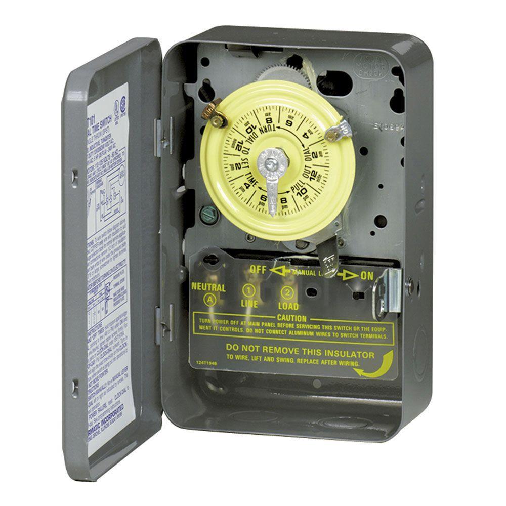
The Intermatic DT101 Digital 24-Hour Time Switch automatically switches loads to a preset daily schedule with to-the-minute
accuracy. Use the DT101 as an ON/OFF timer in applications requiring 24-hour load control such as lighting, air conditioning
systems, pumps, etc. Each load output of the Time Switch can support up to 14 timed ON and 14 timed OFF events per day.
The program can be overridden by pushing the ON/OFF load override button(s). The DT101 Time Switch is designed to directly
switch tungsten or ballast loads up to its rating, and inductive or resistive loads up to 20 A at 120, 208, 240 or 277 VAC.
Time Switch
• Power Consumption: 6.0 W Max.
Switch Ratings
• 20 A Ballast, 120-277 VAC, 60 Hz
• 5 A Tungsten: 120/240 VAC, 60 Hz
• 2 HP, 240 VAC, 60 Hz
• The load output of the Time Switch can support up to
Battery-Powered Clock Operation
alkaline nonrechargeable 1.5 V batteries, supplied)
• 1 minute
• 23 hours, 59 minutes
• 2.5 lb. (1.1 kg)
• TYPE 1 indoor metal enclosure
• Combination 1/2-3/4' size (one on back, one on each
Wire Size